Step 3: Establish a Point-to-Point network connection
This section describes how to set up XBee-PRO XSC RF Modems to transmit and receive data between modems for the different model types: RS-232, RS-485, and USB. To configure your network connection, click on one of the links below according to the model type of your XBee-PRO XSC RF Modem.
RS-232 model
Starting the X-CTU software
- Verify that the XSC RF Modem is connected to the PC by the DB9 cable
- Go to the file where you saved the X-CTU software
- Double-click on X-CTU.exe to start the program
Running the X-CTU software
- Under the PC Settings tab, select the PC serial COM port that corresponds to your RS-232 interface (Communications Port (COM1) in this case).
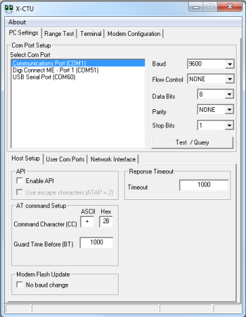
- Set the following values in the Com Port Setup section of X-CTU:
Baud Rate............................9600
Flow Control.......................None
Data Bits..............................8
Parity...................................None
Stop Bits.............................1
 Note: The X-CTU baud rate must match the module's BD parameter for proper communication. The module default is 9600 baud or 19200 baud. If 9600 baud does not work, try 19200 baud. Note: The X-CTU baud rate must match the module's BD parameter for proper communication. The module default is 9600 baud or 19200 baud. If 9600 baud does not work, try 19200 baud.
- The modem's Source Address needs to be assigned. Click the Terminal tab.
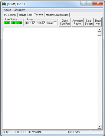
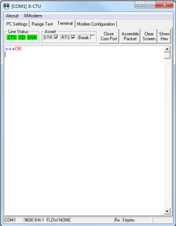
- Enter AT command mode by typing '+++' in the text window. The modem will respond with a red OK as shown below.
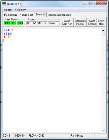
- Type 'atam' and press Enter to assign the MY (Source Address) parameter from the factory-set modem serial number. In this case, the modem responded with 4F4C.
 Warning: This command needs to be entered within a few seconds or the XBee-PRO RF modem will automatically exit command mode and you will need to go back to Step 4. The default command mode timeout is 10 seconds. Warning: This command needs to be entered within a few seconds or the XBee-PRO RF modem will automatically exit command mode and you will need to go back to Step 4. The default command mode timeout is 10 seconds.
Note: You can exit the command mode by typing 'atcn' and pressing Enter.
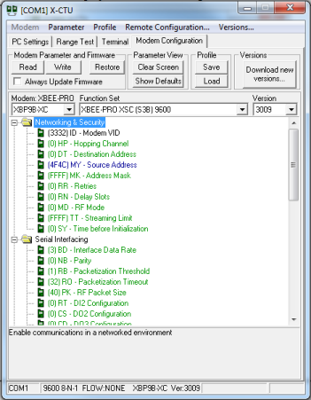
- Select the X-CTU Modem Configuration tab, and then click Read. This will cause X-CTU to display the available settings for the module.
- Connect the other XBee-PRO XSC RF Modems to another computer and repeat steps 1 through 6 for the second modem.
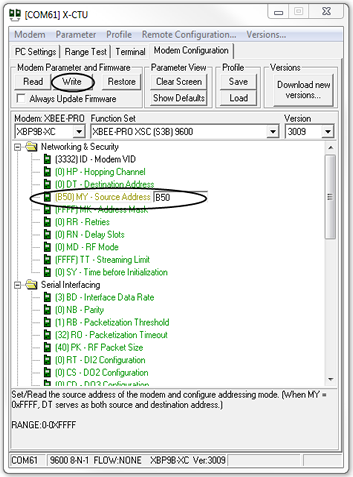
If by chance the Source Address is the same for both modems, change the second modem's address by clicking the Source Address within the Networking & Security folder of the Modem Configuration tab. Type a hexadecimal number up to 4 digits different from the Source Address of the first modem in the box that appears (in the example below, B50 was typed). Then click the Write button (next to the Read button). This will save the settings to the modem.
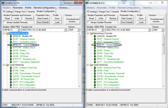
- Within the Networking & Security folder of the Modem Configuration tab, you will find the Source Address that was assigned.
- Select the Destination address of modem 1 and type in the Source Address of modem 2. Select the Destination Address of modem 2 and type in the Source Address of modem 1.
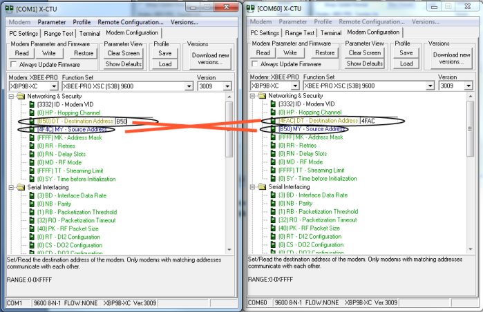
- Click the Write button (next to the Read button). This will save the settings to the modem.
Note: To restore the factory original settings click the Restore button (next to the Write button). This will place the module in the original settings and allow you to connect to a new network.
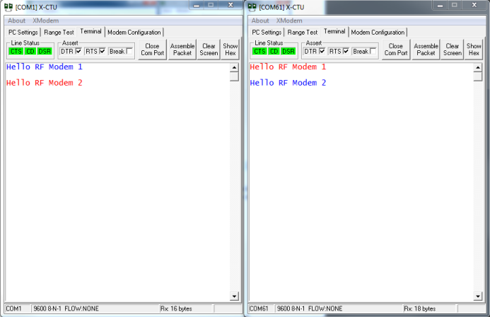
- Select the Terminal tab for each module, click anywhere within the white window, and type any characters that you would like the XSC RF Modem to transmit.
Note: Typed characters in the window of one module will be transmitted to the other module and displayed in that module's X-CTU screen. Characters transmitted are displayed in blue text and characters received are displayed in red text.
 You have just completed Goal #3: Using X-CTU to establish a Point-to-Point network connection between the XBee-PRO XSC RF Modems You have just completed Goal #3: Using X-CTU to establish a Point-to-Point network connection between the XBee-PRO XSC RF Modems
Back to Download X-CTU | Move to Troubleshooting
|