User's Manual
|
|
| Rabbit 4000 Microprocessor User's Manual |
|
7. External Interrupts
7.1 Overview
The Rabbit 4000 has six external interrupts available, and they share two interrupt vectors. In the case of multiple interrupts sharing an interrupt vector, the data register corresponding to the parallel port(s) being used can be read. Each interrupt vector can be set to trigger on a rising edge, a falling edge, or either edge.
The signal on the external interrupt pin must be present for at least three peripheral clock cycles to be detected. In addition, the Rabbit 4000 has a minimum latency of 10 clocks to respond to an interrupt, so the minimum external interrupt response time is three peripheral clock cycles plus 10 processor clock cycles.
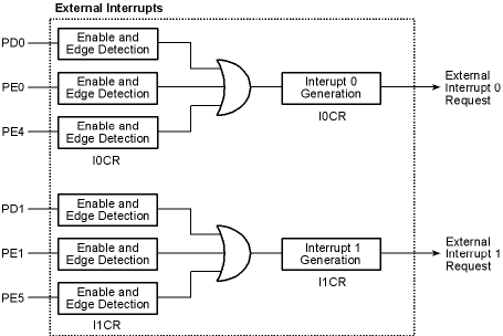
7.2 Block Diagram
7.2.1 Registers
Interrupt 0 Control Register
Interrupt 1 Control Register
7.3 Dependencies
7.3.1 I/O Pins
The external interrupts can be enabled on pins PD0, PD1, PE0, PE1, PE4, and PE5. Each pin is associated with a particular interrupt vector as shown in Table 7-1 below.
Table 7-1. Rabbit 4000 Interrupt Vectors Interrupt 0
Interrupt 1
7.3.2 Clocks
The external interrupts are controlled by the peripheral clock. A pulse must be present for at least three peripheral clock cycles to trigger an interrupt.
7.3.3 Interrupts
An external interrupt is generated whenever the selected edge occurs on an enabled pin. The interrupt request is automatically cleared when the interrupt is handled.
The external interrupt vectors are in the EIR at offsets 0x000 and 0x010. They can be set as Priority 1, 2, or 3 in the appropriate IxCR.
7.4 Operation
The following steps must be taken to enable the external interrupts:
- Write the vector(s) to the interrupt service routine to the external interrupt table.
- Configure IxCR to select which pins are enabled for external interrupts, what edges are detected on each pin, and the interrupt priority.
7.4.1 Example ISR
A sample interrupt handler is shown below.
extInt_isr::
; respond to external interrupt here
; interrupt is automatically cleared by interrupt acknowledge
ipres
ret7.5 Register Descriptions
| Rabbit Semiconductor www.rabbit.com |