User's Manual
|
|
| Rabbit 4000 Microprocessor User's Manual |
|
25. Breakpoints
25.1 Overview
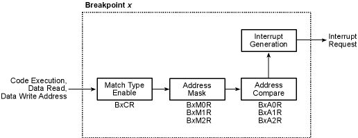
The Rabbit 4000 contains seven hardware breakpoints to support debugging. Each hardware breakpoint consists of a 24-bit address match register and a 24-bit mask register. A breakpoint can be generated on an address match for address execution, data read, data write, or any combination thereof. The mask register serves to mask off selected address bits from the address compare. A "one" in a particular bit position in the mask register inhibits the corresponding bit in the address match register from contributing to the address match condition.
When a match occurs, a Level 3 breakpoint interrupt is generated. Note that this means that breakpoints behave differently when the processor is running at Interrupt Priority 3 — the interrupt is generated but will not be handled until the processor drops to a lower priority.
In most cases, a code execution interrupt will be handled at the end of the instruction in which the match occurred. However, because of the time required to perform a 24-bit address match in the processor, a code execution breakpoint that is set on a single-byte, 2-clock instruction will not yet be enabled at the end of that instruction, and the interrupt will instead occur at the end of the next instruction.
Note that a breakpoint may be forced to be pending by setting the corresponding bit in BDCR. This feature allows a breakpoint request to be used as a virtual single-step request by always setting the appropriate bit in the interrupt handler. There is a particular sequence of instructions required to exit properly when the interrupt is left pending.
DMA transfers are treated as normal data reads and writes, although the DMA transfer will complete before the interrupt is taken.
Breakpoints can be enabled for the User Mode, the System Mode, or both.
Another breakpoint feature is the ability to disable the RST 28h instruction. The RST 28h vector was often used as a breakpoint feature by adding that instruction to code; by enabling a bit in BDCR, the RST 28h instruction will execute as a NOP instead, providing an easy way to disable that type of breakpoint.
Note that hardware breakpoints do not differentiate between memory and I/O accesses. Hardware breakpoints are triggered by both memory and by internal I/O reads and writes. This behavior could potentially make it hard to detect a low-memory situation when using breakpoints if internal I/O reads/writes are occurring, but it allows inadvertent I/O accesses to be identified.
25.1.1 Block Diagram
25.1.2 Registers
25.2 Dependencies
25.2.1 I/O Pins
There are no I/O pins associated with breakpoints.
25.2.2 Clocks
There are no clocks associated with breakpoints.
25.2.3 Other Registers
There are no other registers associated with breakpoints.
25.2.4 Interrupts
When an enabled address match occurs for a given breakpoint, a breakpoint interrupt occurs. The breakpoint that caused the interrupt must be determined by reading BDCR, which also clears the interrupt. Any of the breakpoint interrupts can be enabled by writing to BDCR.
The breakpoint interrupt vector is in the EIR at offset 0x040. It is always set to Interrupt Priority 3, and is the highest priority interrupt; if two Interrupt Priority 3 vectors are pending, the breakpoint interrupt will always be handled first.
25.3 Operation
The following steps must be taken to enable breakpoints:
- Write the vector to the interrupt service routine to the external interrupt table.
- Write the desired breakpoint addresses to the appropriate breakpoint address registers (BxAyR, where x is the breakpoint and y is the byte of the address, 0-2).
- Write an address mask for the given breakpoints (BxMyR).
- Select the breakpoint address match type (execute, data read, data write) by writing to the appropriate BxCR.
- Enable the desired breakpoints by writing to BDCR.
25.3.1 Handling Interrupts
The following actions occur within the interrupt service routine.
- Which breakpoints are pending should be determined by reading BDCR. This also clears the pending breakpoints.
- The desired breakpoint action should be taken.
- If single-step functionality is desired, the breakpoint interrupt should be re-enabled by writing the appropriate bit to BDCR. If this is done, the interrupt handler needs to be exited in a particular manner (see below).
25.3.2 Example ISR
A sample interrupt handler is shown below.
breakpoint_isr::
  push af
  ioi ld a, (BDCR)  ; determine which interrupts are pending and
                    ; clear the interrupt request
; handle all breakpoints here
; reenable any breakpoints by writing to BDCR
  pop af
  ipres        ; you must exit the handler with these two
  ret          ; instructions if you reenabled breakpoints
25.4 Register Descriptions
Breakpoint x Address [7:0].
Breakpoint x Address [15:8].
Breakpoint x Address [23:16].
Breakpoint x Mask [7:0]. (A one in a bit position inhibits the address compare for that bit position.)
Breakpoint x Mask [15:8]. (A one in a bit position inhibits the address compare for that bit position.)
Breakpoint x Mask [23:16]. (A one in a bit position inhibits the address compare for that bit position.
| Rabbit Semiconductor www.rabbit.com |