User's Manual
|
|
| Rabbit 4000 Microprocessor User's Manual |
|
22. Quadrature Decoder
22.1 Overview
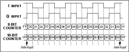
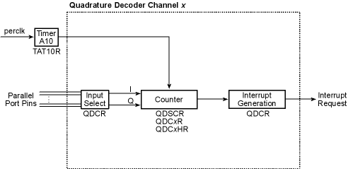
The Rabbit 4000 has a two-channel Quadrature Decoder that accepts inputs via specific pins on Parallel Ports D and E. Each channel has two inputs, the in-phase (I) input and the 90 degree or quadrature-phase (Q) input. An 8 or 10-bit up/down counter counts encoder steps in the forward and backward directions, and provides interrupts when the count goes from 0x00 to 0xFF or from 0xFF to 0x00. An interrupt can occur each time the count overflows or underflows. The Quadrature Decoder contains digital filters on the inputs to prevent false counts. The external signals are synchronized with an internal clock provided by the output of Timer A10.
Each Quadrature Decoder channel accepts inputs from either the upper nibble or lower nibble of Parallel Ports D and E. The I signal is input on an odd-numbered port bit, while the Q signal is input on an even-numbered port bit. There is also a disable selection, which is guaranteed not to generate a count increment or decrement on either entering or exiting the disabled state.
The operation of the counter as a function of the I and Q inputs is shown below.
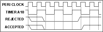
The Quadrature Decoders are clocked by the output of Timer A10, giving a maximum clock rate from perclk/2 down to perclk/512. The time constant of Timer A10 must be fast enough to sample the inputs properly. Both the I and Q inputs go through a digital filter that rejects pulses shorter than two clock period wide. In addition, the clock rate must be high enough that transitions on the I and Q inputs are sampled in different clock cycles. Input capture may be used to measure the pulse width on the I inputs because they come from the odd-numbered port bits. The operation of the digital filter is shown below.
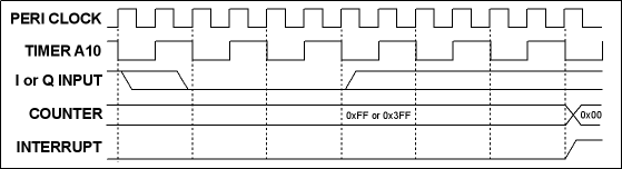
The Quadrature Decoder generates an interrupt when the counter increments from 0xFF (0x3FF in 10-bit mode) to 0x00, or when the counter decrements from 0x00 to 0xFF (0x3FF in 10-bit mode). The timing for the interrupt is shown below. Note that the status bits in the QDCSR are set coincident with the interrupt, and the interrupt and status bits are cleared by reading the QDCSR.
22.1.1 Block Diagram
22.1.2 Registers
Quad Decode Ctrl/Status Register
Quad Decode Control Register
Quad Decode Count 1 Register
Quad Decode Count 1 High Register
Quad Decode Count 2 Register
Quad Decode Count 2 High Register
22.2 Dependencies
22.2.1 I/O Pins
Each Quadrature Decoder channel can accept the two encoder inputs from one of three different locations, as shown in the table below. Each channel can select a different input option. Note that these pins can be used for other peripherals at the same time as the Quadrature Decoder peripheral; one example of this use is to use measure pulse width on the I channels with the input capture peripheral.
Option 1
Option 2
Option 3
22.2.2 Clocks
The 8/10-bit Quadrature Decoder counters are clocked from the output of Timer A10, and can run at rates from the peripheral clock divided by 2 down to the peripheral clock divided by 512 by writing the appropriate value to TAT10R. The clock rate must be high enough that transitions on the inputs are sampled in different clock cycles. In addition, both the I and Q inputs go through a digital filter that rejects pulses shorter than two clock periods wide.
22.2.3 Other Registers
TAT10R
Time constant for Quadrature Decoder clock
22.2.4 Interrupts
Each Quadrature Decoder channel can generate an interrupt whenever the counter increments from 0x0FF (0x3FF in 10-bit mode) to 0x00 or when the counter decrements from 0x000 to 0x0FF (0x3FF for 10-bit mode). The interrupt request is cleared when QDCSR is read.
The Quadrature Decoder interrupt vector is in the IIR at offset 0x190. It can be set as Priority 1, 2, or 3.
The status bits in the QDCSR are set coincident with the interrupt request and are reset when QDCSR is read.
22.3 Operation
The following steps explain how to set up a Quadrature Decoder channel.
- Configure Timer A10 via TAT10R to provide the desired Quadrature Decoder clock speed.
- Configure QDCR to select the input pins for the two channels.
- Reset the counters by writing to QDCSR.
22.3.1 Handling Interrupts
The following steps explain how an interrupt is set up and used.
- Write the vector to the interrupt service routine to the internal interrupt table.
- Configure QDCR to select the interrupt priority (note that interrupts will be enabled once this value is set).
The following actions occur within the interrupt service routine.
- Since a Quadrature Decoder interrupt occurs when the counter rolls over, determine exactly why the interrupt occurred by reading the status bits in QDCSR and adjust any software counters accordingly. This will also clear the interrupt request.
- The current counter value can be read from QDCxR (and QDCxHR if the 10-bit counter is enabled).
22.3.2 Example ISR
A sample interrupt handler is shown below.
qd_isr::
   push af             ; save used registers
   ioi ld a, (QDCSR)   ; clear the interrupt request and get status
   ; perform any necessary software counter adjustments here
   ; read current counter value(s)
   pop af              ; restore used registers
   ipres
   ret
22.4 Register Descriptions
The current value of bits 7-0 of the Quadrature Decoder counter is reported.
These bits are reserved and will always read as zeros.
The current value of bits 9-8 of the Quadrature Decoder counter is reported.
| Rabbit Semiconductor www.rabbit.com |