User's Manual
 |
|
| Rabbit 2000 Microprocessor User's Manual |
|
13. Rabbit Slave Port
When a Rabbit microprocessor is configured as a slave, parallel port A and certain other data lines are used as communication lines between the slave and the master. The slave unit is a Rabbit configured as a slave. The master can be another Rabbit or any other type of processor. Rabbits configured as slaves can themselves have slaves.
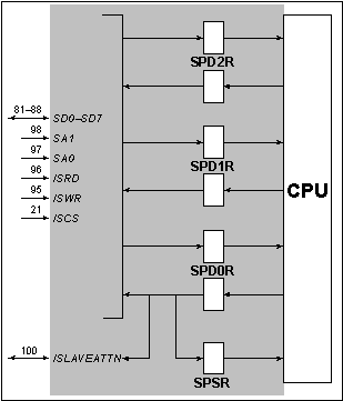
The master and slave communicate with each other via the slave port. The slave port is a physical device that includes data registers, a data bus, and various handshaking lines. The slave port is a part of the slave Rabbit, but logically it is an independent device that is used to communicate between the two processors. Figure 13-1 shows a diagram of the slave port.

The slave port has three data registers for each direction of communication. Three registers, SPD0R, SPD1R, and SPD2R, can be written by the master and read by the slave. Three different registers, also named SPD0R, SPD1R, and SPD2R, can be written by the slave and read by the master. The same names are used for different registers since it is usually clear from the context which register is meant. If it is necessary to distinguish between registers, we will refer to the registers as "SPD0R writable by the slave" or "SPD0R writable by the master."
A status register can be read by either the slave or the master. The status register has full/ empty bits for each of the six registers. A data register is considered full when it is written to by whichever side is capable of writing to it. If the same register is then read by either side it is considered to be empty. The flag for that register is thus set to a "1" when the register is written to, and the flag is set to a "0" when the register is read.
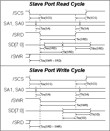
The registers appear to be internal I/O registers to the slave. To the master, at least for a Rabbit master, the registers appear to be external I/O registers. The figure below shows the sequence of events when the master reads/writes the slave port registers.

The following table explains the parameters used in Figure 13-2.
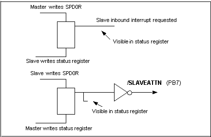
The two SPD0R registers have special functionality not shared by the other data registers. If the master writes to SPD0R, an inbound interrupt flip-flop is set. If slave port interrupts are enabled, the slave processor will take a slave port interrupt. If the slave writes to the other SPD0R register, the slave attention line (/SLAVEATTN, pin 100) is asserted (driven low) by the slave processor. This line can be used to create an interrupt in the master. Either side that is interrupted can clear the signal that is causing an interrupt request by writing to the slave port status register. The data bits are ignored, but the flip-flop that is the source of the interrupt request is cleared. Figure 13-3 shows a logical schematic of this functionality.

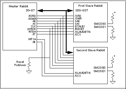
Figure 13-4 shows a sample connection of two slave Rabbits to a master Rabbit. The master drives the slave reset line for both slaves and provides the main processor clock from its own clock. There is no requirement that the master and slave share a clock, but doing so makes it unnecessary to connect a crystal to the slaves. Each Rabbit in Figure 13-4 has to have RAM memory. The master must also have flash memory. However, the slaves do not need nonvolatile memory since the master can cold boot them over the slave port and download their program. In order for this to happen, the SMODE0 and SMODE1 pins must be properly configured as shown in Figure 13-4 to begin a cold boot process at the end of the slave reset.

The slave port lines are shown in Figure 13-1. The function of these lines is described below.
- SD0-SD7--These are bidirectional data lines, and are generally connected to the data bus of the master processor. Multiple slaves can be connected to the data bus. The slave drives the data lines only when /SCS and /SRD are both pulled low.
- SA1, SA0--These are address lines used to select one of the four data registers of the slave interface. Normally these lines are connected to the low-order address lines of the master. The master always drives these lines which are always inputs to the slave.
- /SCS--Input. Slave chip select. The slave ignores read or write requests unless the chip select is low. If a Rabbit is used as a master, this line can be connected to one of the master's programmable chip select lines /I0-/I7.
- /SRD--Input. If /SCS is also low, this line pulled low causes the contents of the register selected by the address lines to be driven on the data bus. If a Rabbit is used as a master, this line is normally connected to the global I/O read strobe /IORD.
- /SWR--Input. If /SCS is also low, this line causes the data bits on the data bus to be clocked into the register selected by the address lines on the rising edge of /SWR or /SCS, whichever rises first. If a Rabbit is used as a master, this line is normally connected to the global I/O write strobe /IOWR.
- /SLAVEATTN--This line is set low (asserted) if the slave writes to the SPD0R register. This line is set high if the master writes anything to the slave status register. This line is usually connected to cause the master to be interrupted when it goes low.
The data lines of the slave port are shared with parallel port A that uses the same package pins. The slave port can be enabled, and parallel port A be disabled, by storing an appropriate code in the slave port control register (SCR). After the processor is reset, all the pins belonging to the slave interface are configured as parallel-port inputs unless (SMODE1, SMODE0) are set to (0,1), in which case the slave port is enabled after reset and the slave starts the cold-boot sequence using the slave port.
13.1 Hardware Design of Slave Port Interconnection
Figure 13-4 shows a typical circuit diagram for connecting two slave Rabbits to a master Rabbit. The designer has the option of cold-booting the slave and downloading the program to RAM on each cold start. Another option is to configure the slave with both RAM and flash memory. In this case, the slave will only have the program downloaded for maintenance or upgrades. Usually, the flash would not be written to on every startup because of the limited number of lifetime writes to flash memory. The slaves' reset in Figure 13-4 is under the program control of the master. If the master is reset, the slave will also be reset because the master's drive of the reset line will be lost on reset and the pulldown resistor will pull the slaves' resets low. This may be undesirable because it forces the slave to crash if the master crashes and has a watchdog timeout.
13.2 Slave Port Registers
The slave port registers are listed in Table 13-1. These registers, each of which is actually two separate registers, one for read and one for write, are accessible to the slave at the I/O addresses shown in the table and they are accessible to the master at the external address shown which specifies the value of the slave address (SA0, SA1) input to the slave when the master reads or writes the registers. The register that can be written by the slave can only be read by the master and vice versa. If one side were to attempt to read a register at the same time that the other side attempted to write the register the result of the read could be scrambled. However, the protocols and handshaking bits used in communication are normally such that this never happens.
If the user for some reason wants to depart from the suggested protocols and poll a register while waiting for the other side to write something to the register, the user should be aware that all the bits might not change at the exact same time when the result changes, and a transitional value could be read from the register where some bits have changed to the new value and others have not. To avoid being confused by a transitional value, the user can read the register twice and make sure both values are the same before accepting the value, or the user can test only one bit for a change. The transitional value can only exist for one read of the register, and each bit will have its old value change to the new value at some point without wavering back and forth. The existence of a transitional value could be very rare and has the potential to create a bug that happens often enough to be serious, but so infrequently as to be difficult to diagnose. Thus, the user is cautioned to avoid this situation.
Table 13-2 describes the slave port control register.
The functionality of the bits is as follows:
- Bit 7--If set to "0," the cold-boot feature will be enabled. Normally this bit is set to a "1" after the cold boot is complete. The cold boot for the slave port is enabled automatically if (SMODE1, SMODE0) lines are set to (0,1) after the reset ends. This features disables the normal operation of the processor and causes commands to be accepted via the slave port register SPD0R. These commands cause data to be stored in memory or I/O space. When the master that is managing the cold boot has finished setting up memory and I/O space, the (SMODE1, SMODE0) pins are changed to code (0,0), which causes execution to start at address zero. Typically this will start execution of a secondary boot program. At some point, bit 7 will be set to a "1" so that the SMODEx pins can be used as normal input pins.
- Bits 6,5--May be used to read the input pins SMODE, SMODE0.
- Bits 3,2--Bit 3 enables the slave port when set to a "1," disabling parallel port A and various other port lines. Bit 3 is automatically set to a "1" if a cold boot is done via the slave port. If bit 3 is "0," then bit 2 controls whether parallel port A is an input (bit 2 = 0) or an output (bit 2 = 1).
- Bits 1,0--This 2-bit field sets the priority of the slave port interrupt. The interrupt is disabled by (0,0).
Table 13-3 describes the slave port status register. The status register has 6 bits that are set if the particular register is full. That means that the register has been written by the processor that can write to it but it has not been read by the processor that can read it. The bits for SPD0R are used to control the slave interrupt and the handshaking lines as shown in Figure 13-3.
13.3 Applications and Communications Protocols for Slaves
The communications protocol used with the slave port depends on the application. A slave processor may be used for various reasons. Some possible applications are listed below.
Keep in mind that the Rabbit can also be operated as a slave processor via a serial port and some of the protocols will work well via a serial communications connection. If a serial connection is used, the protocol becomes more complicated if errors in transmission need to be taken into account. If the physical link can be controlled so that transmission errors do not occur, a realistic possibility if the interconnection environment is controlled, the serial protocol is simpler and faster than if error correction needs to be taken into account.
13.3.1 Slave Applications
- Motion Controller--Many types of motion control require fast action, may be compute-intensive or both. Traditional servo system solutions may be overly expensive or not work very well because of system nonlinearities. The basic communications model for a motion controller is for the master to send short messages--positioning commands--to the slave. The slave acknowledges execution of the commands and reports exception conditions.
- Communications Protocol Processor--Communications protocols may be very complex, may require fast responses, or may be compute-intensive.
- Graphics Controller--The Rabbit can be used to perform operations such as drawing geometric figures and generating characters.
- Digital Signal Processing--Although the Rabbit is not a speciality digital signal processor, it has enough compute speed to handle some types of jobs that might otherwise require a speciality processor. The slave processor can process data to perform pattern recognition or to extract a specific parameter from a data stream.
13.3.2 Master-Slave Messaging Protocol
In this protocol the master sends messages to the slave and receives an acknowledgement message. The protocol can be polled or interrupt driven. Generally, the master sends a message that has a message type code, perhaps a byte count, and the text of the message. The slave responds with a similar message as an acknowledgement. Nothing happens unless the master sends a message. The slave is not allowed to initiate a message, but the slave could signal the master by using a parallel port line other than /SLAVEATN or by placing data in one of the registers the master can read without interfering with the message protocol.
The master sends a message byte by storing it in SPD0R. The slave notices that SPD0R is full and reads the byte. When the master notices that SPD0R is empty because the slave read it, the master stores the next byte in SPD0R. Either side can tell if any register is empty or full by reading the status register. When the slave acknowledges the message with a reply message, the process is reversed. To perform the protocol with interrupts, a slave interrupt can be generated each time the slave receives a character. The slave can acknowledge the master by reading SPD0R if the master is polling for the slave response to each character. If the master is to be interrupted to acknowledge each character, the slave can create an interrupt in the master by storing a dummy character in SPD0R to create a master interrupt, assuming that the /SLAVEATTN line is wired to interrupt the master. The acknowledgement message works in a similar manner, except that the master writes a dummy character to interrupt the slave to say that it has the character.
Several problems can arise if there are dual interrupts for each character transmitted. One problem is that the message transmission rate will free run at a speed limited by the interrupt latency and compute speed of each processor. This could consume a high percentage of the compute resources of one or both processors, starving other processes and especially interrupt routines, for compute time. If this is a problem, then a timed interrupt can be used to drive the process on one side, thus limiting the data transmission rate.
Another solution, which may be better than limiting the transmission rate, is to use interrupts only for the first byte of the message on the slave side, and then lower the interrupt priority and conduct the rest of the transaction as a polled transaction. On the master side the entire transaction can be a polled transaction. In this case, the entire transaction takes place in the interrupt routine on the slave, but other interrupts are not inhibited since the priority has been lowered.
A typical slave system consists of a Rabbit microprocessor and a RAM memory connected to it. The clock can be provided either by connecting a crystal, or crystals to the slave or by providing an external clock, which could be the master's clock. The reset line of the slave would normally be driven by the master. At system startup time the master resets the slave and cold boots it via the slave port. (The SMODE pins must be configured for this.) Once the software is loaded into the slave, the slave can begin to perform its function.
As a simple example, suppose that the slave is to be used as a four-port UART. It has the capability to send or receive characters on any of its four serial ports. Leaving aside the question of setup for parameters, such as the baud rate, we could define a protocol as follows.
- SPD0R readable by master is a status register with bits indicating which of the four receivers and four transmitters is ready, that is, has a character received or is ready to send a character.
- SPD0R writable by the master is a control register used to send commands to the slave.
- SPD1R is used to send or receive data characters or control bytes.
- The line /SLAVEATTN is wired to the external interrupt request of the master so that the master is interrupted when the slave writes to SPD0R. Typically the slave will write to SPD0R when there is a change of status on one of the serial ports.
The slave can interrupt the master at any time by storing to SPD0R. It will do this every time an enabled transmitter is ready to accept a character or every time an enabled receiver receives a character. When it stores to SPD0R, it will store a code indicating the reason for the interrupt, that is, receive or transmit and channel number. If the cause is receive, the received character will also be placed in SPD1R writable by the slave. When the master is interrupted for any reason, the master will sneak a peek at SPD0R by reading SPSR. If the interrupt is caused by a receive character, it will remove the character from SPD1R and read SPD0R to handshake with the slave.
If the master is interrupted for transmitter ready, as determined by the sneak peek, it will place the outgoing character in SPD1R and write a code to SPD0R indicating transmit and channel number. This will cause the slave to be interrupted, and the slave will take the character and handshake by reading SPD0R. This handshake does not interrupt the master.
| Rabbit Semiconductor www.rabbit.com |