|
|
| << Previous | Index | Next >> | |
| | |
This chapter gives an overview of the ZigBee specification. ZigBee, its specification and promotion, is a product of the ZigBee Alliance. The Alliance is an association of companies working together to ensure the success of this open global standard.
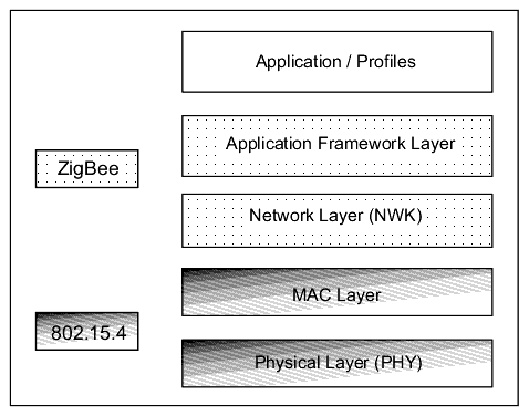
ZigBee is built on top of the IEEE 802.15.4 standard. ZigBee provides routing and multi-hop functions to the packet-based radio protocol.
4.1 Logical Device Types
The ZigBee stack resides on a ZigBee logical device. There are three logical device types:
It is at the network layer that the differences in functionality among the devices are determined. See Table 4-1 for more information. It is expected that in a ZigBee network the coordinator and the routers will be mains-powered and that the end devices can be battery-powered.
In a ZigBee network there is one and only one coordinator per network. The number of routers and/or end devices depends on the application requirements and the conditions of the physical site.
Within networks that support sleeping end devices, the coordinator or one of the routers must be designated as a Primary Discovery Cache Device. These cache devices provide server services to upload and store discovery information, as well as respond to discovery requests, on behalf of the sleeping end devices.
4.2 ZigBee Stack Layers
As shown in Figure 4.1, the stack layers defined by the ZigBee specification are the network and application framework layers. The ZigBee stack is loosely based on the OSI 7-layer model. It implements only the functionality that is required in the intended markets.
4.2.1 Network (NWK) Layer
The network layer ensures the proper operation of the underlying MAC layer and provides an interface to the application layer. The network layer supports star, tree and mesh topologies. Among other things, this is the layer where networks are started, joined, left and discovered.
When a coordinator attempts to establish a ZigBee network, it does an energy scan to find the best RF channel for its new network. When a channel has been chosen, the coordinator assigns the logical network identifier, also known as the PAN ID, which will be applied to all devices that join the network.
A node can join the network either directly or through association. To join directly, the system designer must somehow add a node's extended address into the neighbor table of a device. The direct joining device will issue an orphan scan, and the node with the matching extended address (in its neighbor table) will respond, allowing the device to join.
To join by association, a node sends out a beacon request on a channel, repeating the beacon request on other channels until it finds an acceptable network to join.
The network layer provides security for the network, ensuring both authenticity and confidentiality of a transmission.
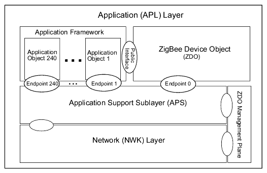
4.2.2 Application (APL) Layer
The APL layer is made up of several sublayers. The components of the APL layer are shown in Figure 4.2. and discussed below. The ovals symbolize the interface, called service access points (SAP), between different sublayer entities.
4.2.2.1 Application Support Sublayer (APS)
The APS sublayer is responsible for:
binding tables
message forwarding between bound devices
group address definition and management
address mapping from 64-bit extended addresses to 16-bit NWK addresses
fragmentation and reassembly of packets
reliable data transport
The key to interfacing devices at the need/service level is the concept of binding. Binding tables are kept by the coordinator and all routers in the network. The binding table maps a source address and source endpoint to one or more destination addresses and endpoints. The cluster ID for a bound set of devices will be the same.
As an example, consider the common control problem of maintaining a certain temperature range. A device with temperature-sensing circuitry can advertise its service of providing the temperature as a
READ_TEMPERATUREcluster ID. A controller (for a furnace or a fan, perhaps) could discover the temperature sensor device. The binding table would identify the endpoint on the temp sensor that accepts theREAD_TEMPERATUREcluster ID, for example. One temperature sensor manufacturer might have endpoint 0x11 support this cluster ID, while another manufacturer might use endpoint 0x72 to support this cluster ID. The controller would have to discover both devices and would then create two binding table entries, one for each device. When the controller wants to read the temperature of all sensors, the binding table tells it which address and endpoint theREAD_TEMPERATUREpacket should be sent to.4.2.2.2 Application Framework
The application framework is an execution environment for application objects to send and receive data. Application objects are defined by the manufacturer of the ZigBee-enabled device. As defined by ZigBee, an application object is at the top of the application layer and is determined by the device manufacturer. An application object actually implements the application; it can be a light bulb, a light switch, an LED, an I/O line, etc. The application profile (discussed in Section 4.4) is run by the application objects.
Each application object is addressed through its corresponding endpoint. Endpoint numbers range from 1 to 240. Endpoint 0 is the address of the ZigBee Device Object (ZDO). Endpoint 255 is the broadcast address, i.e., message are sent to all of the endpoints on a particular node. Endpoints 241 through 254 are reserved for future use.
ZigBee defines function primitives, not an application programming interface (API).
4.2.2.3 ZigBee Device Object (ZDO)
The ZDO is responsible for overall device management, specifically it is responsible for:
initializing the APS sublayer and the NWK layer
defining the operating mode of the device (i.e., coordinator, router, or end device)
device discovery and determination of which application services the device provides
initiating and/or responding to binding requests
security management
Device discovery can be initiated by any ZigBee device. In response to a device discovery inquiry end devices send their own IEEE or NWK address (depending on the request). A coordinator or router will send their own IEEE or NWK address plus all of the NWK addresses of the devices associated with it. (A device is associated with a coordinator or router if it is a child node of the coordinator or router.)
Device discovery allows for an ad-hoc network. It also allows for a self-healing network.
Service discovery is a process of finding out what application services are available on each node. This information is then used in binding tables to associate a device offering a service with a device that needs that service.
4.3 ZigBee Addressing
Before joining a ZigBee network (i.e., a LR-WPAN), a device with an IEEE 802.15.4-compliant radio has a 64-bit address. This is a globally unique number made up of an Organizationally Unique Identifier (OUI) plus 40 bits assigned by the manufacturer of the radio module. OUIs are obtained from IEEE to ensure global uniqueness.
When the device joins a Zigbee network, it receives a 16-bit address called the NWK address. Either of these addresses, the 64-bit extended address or the NWK address, can be used within the PAN to communicate with a device. The coordinator of a ZigBee network always has a NWK address of "0."
ZigBee provides a way to address the individual components on the device of a node through the use of endpoint addresses. During the process of service discovery the node makes available its endpoint numbers and the cluster IDs associated with the endpoint numbers. If a cluster ID has more than one attribute, the command is used to pass the attribute identifier.
4.3.1 ZigBee Messaging
After a device has joined the ZigBee network, it can send commands to other devices on the same network. There are two ways to address a device within the ZigBee network: direct addressing and indirect addressing.
Direct addressing requires the sending device to know three kinds of information regarding the receiving device:
Indirect addressing requires that the above three types of information be committed to a binding table. The sending device only needs to know its own address, endpoint number and cluster ID. The binding table entry supplies the destination address(es) based on the information about the source address.
The binding table can specify more than one destination address/endpoint for a given source address/endpoint combination. When an indirect transmission occurs, the entire binding table is searched for any entries where the source address/endpoint and cluster ID matches the values of the transmission. Once a matching entry is found, the packet is sent to the destination address/endpoint. This is repeated for each entry where the source endpoint/address and clusterID match the transmission values.
4.3.2 Broadcast Addressing
There are two distinct levels of broadcast addresses used in a ZigBee network. One is a broadcast packet with a MAC layer destination address of 0xFFFF. Any transceiver that is awake will receive the packet. The packet is re-transmitted three times by each device, thus these types of broadcasts should only be used when necessary.
The other broadcast address is the use of endpoint number 0xFF to send a message to all of the endpoints on the specified device.
4.3.3 Group Addressing
An application can assign multiple devices and specific endpoints on those devices to a single group address. The source node would need to provide the cluster ID, profile ID and source endpoint.
4.4 ZigBee Application Profiles
What is a ZigBee profile and why would you want one? Basically a profile is a message-handling agreement between applications on different devices. A profile describes the logical components and their interfaces. Typically, no code is associated with a profile.
The main reason for using a profile is to provide interoperability between different manufacturers. For example, with the use of the Home Lighting profile, a consumer could use a wireless switch from one manufacturer to control the lighting fixture from another manufacturer.
There are three types of profiles: public (standard), private and published. Public profiles are managed by the ZigBee Alliance. Private profiles are defined by ZigBee vendors for restricted use. A private profile can become a published profile if the owner of the profile decides to publish it.
All profiles must have a unique profile identifier. You must contact the ZigBee Alliance if you have created a private profile in order to be allocated a unique profile identifier.
A profile uses a common language for data exchange and a defined set of processing actions. An application profile will specify the following:
set of devices required in the application area
functional description for each device
set of clusters to implement the functionality
which clusters are required by which devices
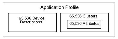
A device description specifies how a device must behave in a given environment. Each piece of data that can be transferred between devices is called an attribute. Attributes are grouped into clusters. Figure 4.3 illustrates the relative relationships of these entities and the maximum number that can exist theoretically per application profile.
All clusters and attributes are given unique identifiers. Interfaces are specified at the cluster level. There are input cluster identifiers and output cluster identifiers.
At time of this writing, the following public profiles are available:
Commercial building automation
Home automation
Industrial plant monitoring
Wireless sensor applications
Smart energy
4.4.1 ZigBee Device Profile
The ZigBee Device Profile is a collection of device descriptions and clusters, just like an application profile. The device profile is run by the ZDO and applies to all ZigBee devices. The ZigBee Device Profile is defined in the ZigBee Application Level Specification. It serves as an example of how to write an application profile.
| An Introduction to ZigBee | << Previous | Index | Next>> | rabbit.com |