


Ethernet Connection
![]()
Ethernet Connection


![]()
![]()


Table of contents:
Section 1. Overview
Section 2. Setting Up the Local “Master” Digi One IA RealPort
Section 3. Setting Up the Remote “Slave” Digi One IA RealPort
Section 4. Sample PLC Program
Section
1. Overview
This document is provided as a supplement to the Digi One IA RealPort Serial to Ethernet Gateway Quickstart Guide supplied by Omron. The initial setup and configuration of the RealPort is explained in that document. This document describes specifically how to setup a serial tunnel between 2 Omron devices. This enables a PLC to send and receive messages to and from another PLC, temperature controller, etc. using the Host Link or Compoway F protocols. This connection is referred to as a “serial tunnel”.
Section
2. Setting Up the Local “Master”
Digi One IA RealPort.
1.
Install the Digi RealPort Remote software by running Setup.exe on the
supplied CD.

2.
From the above screen, select your computer Operating System
(Currently only Windows NT, 2000, and XP are supported), Hardware (Digi
One), and Software (Digi Port Authority – Remote).
Then click Install Software.

3.
Select the installation location, and click Next.

4.
Select the program folder and click Next.

5.
When the installation is complete, click Finish (leave Launch Digi
Port Authority – Remote checked)

6.
In the above configuration window, click Discover to allow the Digi Port
Authority Remote software to search for the connected hardware.

7.
The software should report that a device without an IP address has been
detected. Click OK. If
the software did not find the hardware, check the power connection and Ethernet
connection to the Digi One IA RealPort device and try the Discover option again.
8.
In the configuration software, click Configure.

9.
Enter the IP address, Subnet, and Gateway (if applicable) for the
hardware. If uncertain of these
parameters, contact your network administrator.
Click OK.
10.
Wait while the software applies the settings, and tests the
device.
11.
The configuration window will appear again, with the IP address that you
entered above in the Device window. Click
Configure and login. (The
default user name is “root” and the default password is “dbps”).

12. Set the Device Type to IA.
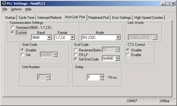
13. Set the Baud Rate, Data bits, Parity, and Stop bits to
match the setting on the port of the local PLC.
Click Submit.

14. Click Industrial Protocols

15. For the protocol select Hostlink and set the mode to Master. Click Submit.
16. Click IA route config...

17. Click Add Destination.

18. Click Unconfigured.

19. Add a Description (optional, but not functionally necessary)
20. Select Network Destination and enter the IP address of the other Digi One IA RealPort that you wish to communicate with (the one on the other end of the serial bridge)
21. Select TCP.
22. Click Advanced. Click Submit.
23. Click Admin. Click Reboot.
Section 3. Setting Up the Remote "Slave” Digi One IA RealPort
Verify that the Baud Rate, Data Bits, Parity, and Stop Bits match the remote device (For Example: the device attached to the remote Digi One IA RealPort).
Verify that the protocol is set to the appropriate protocol, and that the remote Digi One IA RealPort is set for Slave mode.
NOTE: The Baud Rate, Data Bits, Parity, and Stop Bits do not have
to match on each end of the serial tunnel.
They only have to match the serial device that each Digi One IA RealPort
is attached to. (For Example: one
PLC could communicate at 19,200 and the other could communicate at 9600).
Section 4. Example PLC Program
Example CPM2C program to read 10 data memory locations from
another PLC every 1 second starting at DM0000 in the remote PLC and storing the
received data in DM100 in the local PLC.


Local CPM2C Host Link Port Setup
Local CPM2C Data Memory Settings for the Host Link command to send to the remote PLC. The data shown represents a Host Link command to read 1 Data Memory Location starting at DM0000.
NOTE: The
view is set to ASCII (as shown by the
![]() ). Remember to transfer this data
to the PLC.
). Remember to transfer this data
to the PLC.
