Notice the devices are connected via serial ports to Digi One device servers. Devices 1 and 2 can be any UDP serial destination. Up to 64 can be defined. The PC could be any device that needs to send serial data to all destination devices.
Configuring the Digi One
Single Port (Digi One IA) for
UDP Multicast
UDP Multicast can
be used to send serial data from one host to many devices at the same time.
Here are a few examples of how it maybe
implemented:
q Transmit the time or a message to several displays devices simultaneously.
q Console monitoring.
q
Stock and Newswire
tickers.
q Send control information to many PLCs simultaneously.
This document
outlines how to set up a simple UDP serial Multicast Source (Sending
Device) to two UDP Destination Devices using any of the Digi device servers that
support UDP Multicast. Up to 64
destinations are supported.
NOTE: UDP is a connectionless protocol. This means data is sent without the protocol ensuring its reliable delivery. If reliable transmission is required, consider using TCP based communication, such as TCP sockets, RealPort or an IA protocol.
UDP does have some advantages over TCP. The main advantage is that it requires less network overhead. This is mainly due to UDP not requiring an acknowledgement from the receiving device, thus lost packets will not be retransmitted. For example, if a sign does not properly receive the time, is it necessary to have the time retransmitted, if time will be updated again in a second or a minute?
F
Refer to the Digi Install
and Configuration Guides and to http://support.digi.com for more information
on setting up the Digi One
device servers.
Let’s first take a look at a sample UDP Multicast setup:
Notice the devices are connected via serial ports to Digi One device
servers. Devices 1 and 2 can be any
UDP serial destination. Up to 64
can be defined. The PC could be any
device that needs to send serial data to all destination devices.
Serial data is encapsulated from the sender (or source) into Ethernet / UDP. The Digi One device server (shown as 172.16.5.51 above) then multicasts the data to the other Digi One device servers designated as recipients (or destination devices). The received data is then converted back to serial data and sent out each device server’s serial port to the attached devices.
IP addresses must be assigned to each Digi One device server. From the factory, the units come with DHCP enabled. Depending on the product, there are several ways to assign an IP address. Here are three common ways to assign the IP address:
q
DHCP – default setting. If
no DHCP server is available the address will be 0.0.0.0.
NOTE: DHCP can be disabled.
q Digi Discovery Protocol (ADDP) – ADDP comes as part of the Digi setup program (either Digi Port Authority Remote or Digi Device and Terminal Server Setup) included on the Access Resource CD. This can be used to find both configured (with IP address) and un-configured (no IP address) Digi One device servers on the local LAN.
q ARP-PING – Add an entry to the ARP table on a PC using the MAC address of the unit; then ping the unit. As an example from a Windows PC:
arp
-s 192.168.2.2 00-40-9D-00-00-00
ping 192.168.2.2]
F Refer to the Digi One Device Server documentation and to http://support.digi.com for more information on assigning an IP addresses.
1. If this is the initial configuration of the Digi
One Single Port (Digi One IA), launch
the Setup Wizard (dgcfgwiz.exe). The Setup Wizard can be
located in the driver files for the Digi One SP/IA.
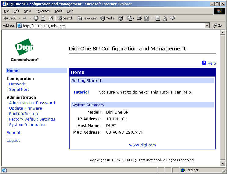
2. If you have already configured your Digi One Single Port (Digi One IA),
you can follow the Web Interface configuration below.
NOTE: You will need to be on the latest
firmware version to follow this setup example.
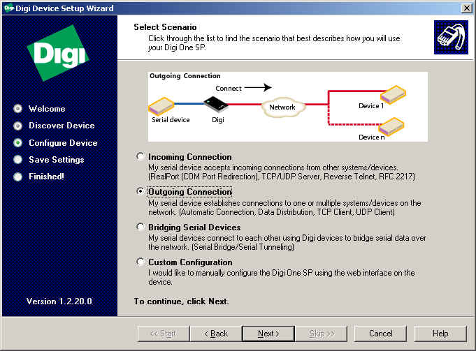
The Outgoing
Device is basically the sending device. Any
serial data entering the serial port will be forwarded to the target (Incoming) device servers via Ethernet.
The target servers are defined later in this setup procedure.
Use this procedure if this is the initial configuration of your Digi One Single Port (Digi One IA) Device Server.
1.
Launch
the Setup Wizard (dgcfgwiz.exe). The Setup Wizard can be located in the
driver files for the Digi One SP/IA Device.
2. Click Next>
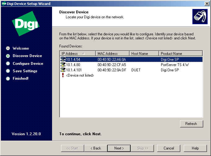
3. Select your Digi Device from the list of Discovered Devices and
click Next>. If this is the initial configuration of the Digi
SP/IA Device, you may not have an IP Address assigned, but
will be prompted to enter one later in this setup.
NOTE: If you do not see your device in the list, click !
<Device not listed> for troubleshooting assistance.
4. If this is the initial configuration of the Digi SP/IA
Device, you will be required to configure the Network Settings.
NOTE: If you have already configured your Network
Settings, you may want to review the settings for accuracy.
Click Next>.
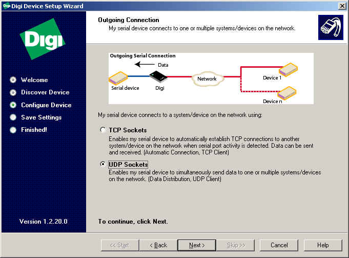
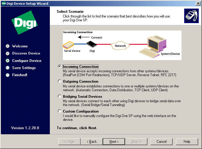
5. Select the radio button next to Outgoing Connection. Click Next>.
6. You will now need to specify how your serial device will
connect to your network device (TCP or UDP). In this
case we will choose UDP. Click Next>.
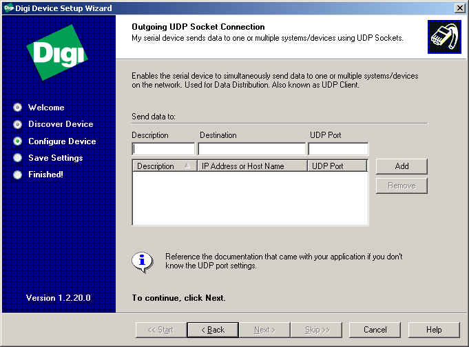
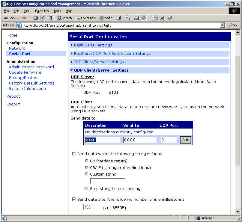
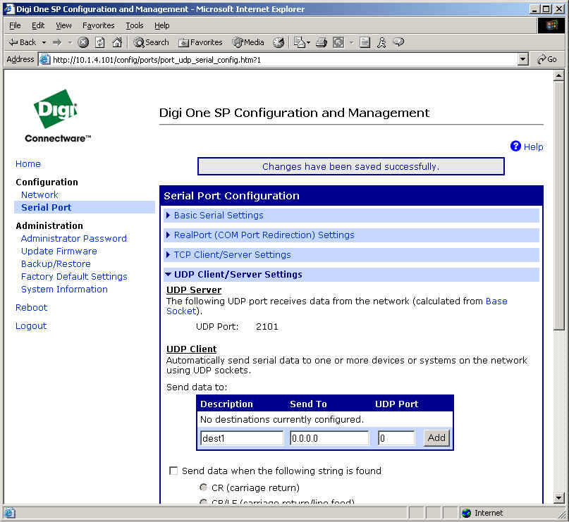
7. Under the Send data to:, specify the following:
A. Description: Give a name to your setup.
B. Destination: Enter the IP Address of the device you are
sending data to.
C. UDP Port: Is the UDP port to use, which is determined by the destination system.
:
NOTE: Here are some tips
on specifying port numbers:
-Use the port required by the application on the destination
system you are running.
-For a raw connection to the serial port on another Digi device, use 2101, unless the default configuration has been changed.
D. Click Add.
E. Repeat if you have multiple destinations you
will be sending data to.
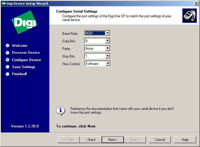
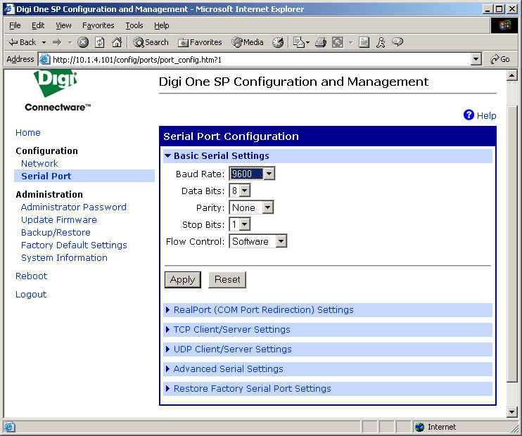
8. Configure the port settings in the following window to match
the requirements of the peripheral device you are connecting
to the Digi One SP/IA serial port. Click Next>.
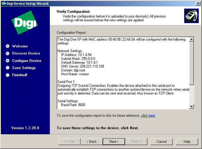
9. You will then be prompted to verify your configuration.
If everything appears accurate, click Next>.
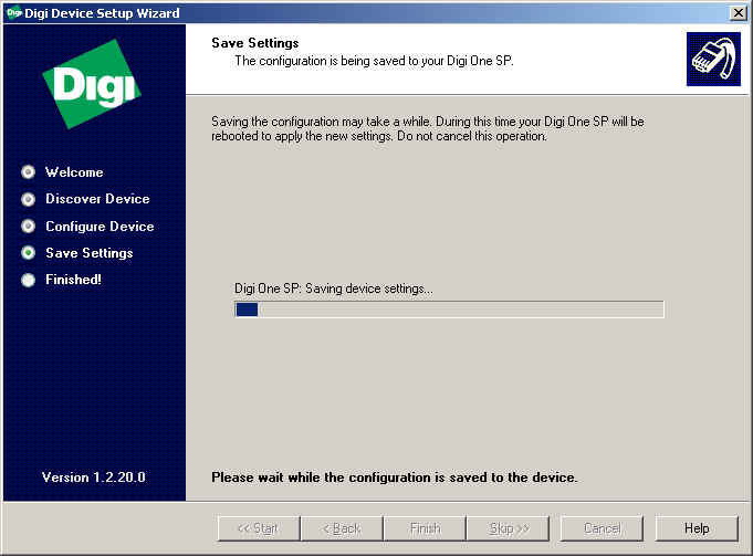
10. It will now take a few moments while it writes the new configuration to the
Digi One SP/IA and reboots.
11. If everything is successful, you will see the following message.
If you get an error message, you will want to view
the error report for more information.
NOTE: If you have not already
registered your product, you will want to do so now.
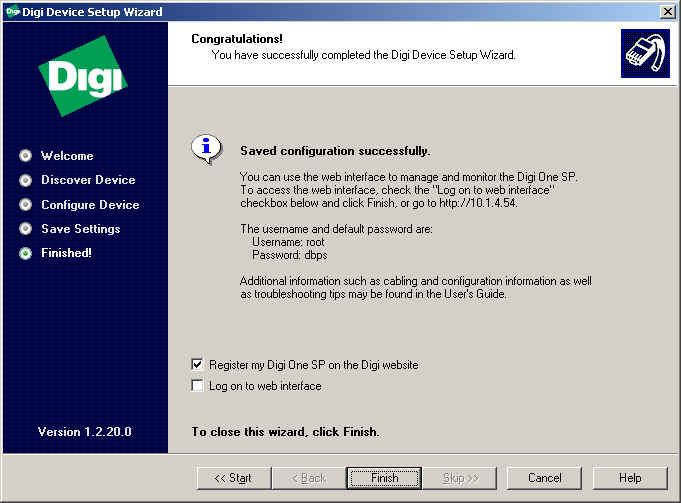
12. You have now successfully configured both Digi One SP/IA Device.
Use this procedure if you have already configured of your
Digi One Single Port (Digi One IA) Device Server.
NOTE: In the diagram
above, the UDP Client (Outgoing Device) has an IP address of 172.16.5.51 and is attached to the
PC.
User Name: root
Password: dbps
1. If this is the initial configuration of the Digi
One Single Port (Digi One IA), launch
the Setup Wizard (dgcfgwiz.exe). The Setup Wizard can be
located in the driver files for the Digi One SP/IA.
2. If you have already configured your Digi One Single Port (Digi One IA),
you can follow the Web Interface configuration below.
NOTE:
You will need to be on the latest firmware version to follow this setup example.
The Incoming Device is basically the receiving device.
Use this procedure if this is the initial configuration of your Digi One Single Port (Digi One IA) Device Server.
1.
Launch
the Setup Wizard (dgcfgwiz.exe). The Setup Wizard can be located in the
driver files for the Digi One SP/IA Device.
2. Click Next>
3. Select your Digi Device from the list of Discovered Devices and
click Next>. If this is the initial configuration of the Digi
SP/IA Device, you may not have an IP Address assigned, but
will be prompted to enter one later in this setup.
NOTE: If you do not see your device in the list, click !
<Device not listed> for troubleshooting assistance.
4. If this is the initial configuration of the Digi SP/IA
Device, you will be required to configure the Network Settings.
NOTE: If you have already configured your Network
Settings, you may want to review the settings for accuracy.
Click Next>.
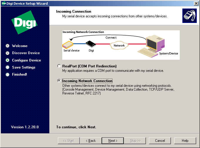
5. Select the radio button next to Incoming Connection. Click Next>.
6. Select Incoming Network Connection and click Next>.
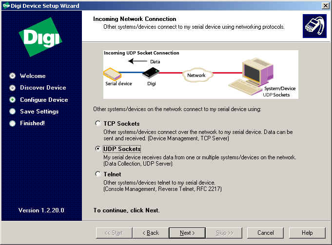
7. You will now need to specify how your serial device
will receive data from the network. In this case we will choose UDP.
Click Next>.
8. Configure the port settings in the following window to match
the requirements of the peripheral device you are connecting
to the Digi One SP/IA serial port. Click Next>.
9. You will then be prompted to verify your configuration.
If everything appears accurate, click Next>.
10. It will now take a few moments while it writes the new configuration to the
Digi One SP/IA and reboots.
11. If everything is successful, you will see the following message.
If you get an error message, you will want to view
the error report for more information.
NOTE: If you have not already
registered your product, you will want to do so now.
12. You have now successfully configured both Digi One SP/IA Device.
Other than assigning the Basic
Serial Settings, the only UDP Server setting is knowing the UDP port number.
number that the UDP Server (Incoming Device) receives on.
In the sample UDP
Multicast setup at the beginning
of this document, the end devices could be PLCs, signs, printers or most any
other serial device. However,
initially testing these devices can be difficult if they are in a remote
location, such as a plant floor.
A simple test bed is to use a
Windows PC running terminal emulation software such as HyperTerminal.
You can use one or multiple PCs to act as the source and destinations.
For example, a two PC setup like the following would work as follows:
On the UDP Server PC (Incoming
Device - Destination), open up two
HyperTerminal sessions – one on COM1 and the other on COM2.
Make sure the port settings for baud rate, parity, etc. match that of the
Digi One SP/IA Device's serial port. Also
make sure no other programs are accessing these ports.
On the UDP Client PC (Outgoing
Device - Source), open a
HyperTerminal session on COM1. Start
typing in the HyperTerminal screen. This
same text should appear on the two HyperTerminal sessions of the UDP Server PC
(Incoming Device - Destination).
The timing of when the text appears depends on the buffer trigger
settings on the UDP Client PC (Outgoing Device - Source).
Another simple test is to send a
large text file from the Source to the Destinations. From a command (DOS) prompt enter the following: type
large_text_file.txt > COM1:
You can also vary the port buffer settings to see how the changes affect the output sent to the terminal window on the Destination PC.