|
|
| << Previous | Index | Next >> | |
| | |
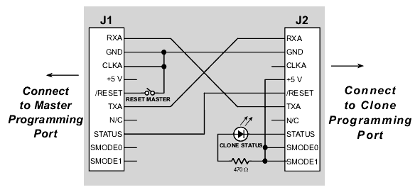
The BIOS supports copying designated portions of flash memory from one controller (the master) to another (the clone). The Rabbit 2000 Cloning Board connects to the programming port of the master and to the programming port of the clone.
8.1 Overview of Cloning
If the cloning board is connected to the master, the signal CLKA is held low. This is detected in the BIOS after the reset ends, invoking the cloning support of the BIOS. If cloning has been enabled in the master's BIOS, it will cold boot the target system by resetting it and downloading a primary boot program. The master then sends the entire BIOS over to the clone, where the boot program receives it and stores it in RAM (just like Dynamic C does when compiling the BIOS). A CRC check of the BIOS is performed on both the master and clone, and the results are compared. The clone is reset again, and the BIOS on the clone begins running. Finally, the master sends the user's program at high speed, and the program is written to the flash memory.
When the designated portion of the flash has been transferred, the clone flashes the cable LED in a distinctive pattern to indicate that the programming is done. At that point the cloning board can be unplugged and plugged into another target. When the master is reset, it will program the next clone.
8.1.1 Evolution of Cloning Support
Over several versions of Dynamic C, cloning has improved in terms of data transfer rates and options that may be set in the BIOS.
For details on both the fast cloning restrictions and options, please see Technical Note 207 "Rabbit 2000 Cloning Board." This document may be found the Rabbit website: www.rabbit.com.rabbit.com/docs/.
8.2 Creating a Clone
Before cloning can occur, the master controller must be readied. Once this is done, any number of clones may be created from the same master.
8.2.1 Steps to Enable and Set Up Cloning
The step-by-step instructions to enable and set up cloning on the master are in Technical Note 207. In brief, the steps break down to: attaching the programming cable, running Dynamic C, making any desired changes to the cloning macros, and then compiling the BIOS and user program to the master.
The only cloning macro that must be changed is
ENABLE_CLONING, since the default condition is cloning is disabled.8.2.2 Steps to Perform Cloning
Once cloning is enabled and set up on the master controller, detach the programming cable and attach the cloning board to the master and the clone. Make sure the master end of the cloning board is connected to the master controller (the cloning board is not reversible) and that pin 1 lines up correctly on both ends. Once this is done, reset the master by hitting Reset on the cloning board. The cloning process will begin.
8.2.3 LED Patterns
The following table describes the LED patterns that may occur on the Cloning Board.
8.3 Cloning Questions
The following sections answer questions about different aspects of cloning.
8.3.1 MAC Address
Some Ethernet-enabled boards do not have the EEPROM with the MAC address, namely the RCM 2100, the RCM 2200 and the BL2000. These boards can still be used as a clone because the MAC address is in the system ID block and this structure is shipped on the board and is not overwritten by cloning unless
CLONE_WHOLE_FLASHandCL_INCLUDE_ID_BLOCKSare both set to one. (Prior to Dynamic C 7.20, the option to overwrite the systemID block did not exist.)If, however, you have a custom-designed board that does not have the EEPROM or the system ID block, you may download a program at:
http://www.rabbit.com/support/feature_downloads.htmlto write the system ID block (which contains the MAC address) to your board.
8.3.2 Different Flash Sizes
Since the BIOS supports a variety of flash types, the flash EPROM on the two controllers do not have to be identical. Cloning works between master and clone controllers that have different-sized flash chips because the master copies its own universal flash driver to the clone. The flash driver determines the particulars of the flash chip that it is driving.
The master controller's BIOS must allocate a memory buffer sufficiently large to work on the target. Prior to Dynamic C version 7.02, the cloning software used root memory for this buffer, which reduces the root memory available to the application program. The size of the buffer is given by the macro
MAX_FLASH_SECTORSIZE. This macro is defined near the top of the\LIB\BIOSLIB\FLASHWR.LIBfile. The default value is 1024 (4096 in older versions). The user can reduce this buffer size to the maximum of the master and target's sector sizes if root data space is a problem, or increase it to 4096 if needed.Starting with Dynamic C version 7.02, the cloning implementation uses
xmemfor the buffer, so root data space will not be a problem; and no changes should be made toFLASHWR.LIB.8.3.3 Design Restrictions
Digital I/O line PB1 should not be used in the design if cloning is to be be used.
| Rabbit 2000 Designer's Handbook |
<< Previous | Index | Next>> | rabbit.com |